
On this page
- What a bench test can and cannot prove
- The three pressure conditions and the published limits
- Where the test points are, and what each one reads
- Electrical pass
- Sensors
- The vacuum step that catches what a gauge cannot
- The bench sequence, with reject criteria at every step
- What still has to happen in the car
- How to read a test sheet that arrives with a unit
- Fluid and assembly figures used around the bench
- Sources and frequently asked questions
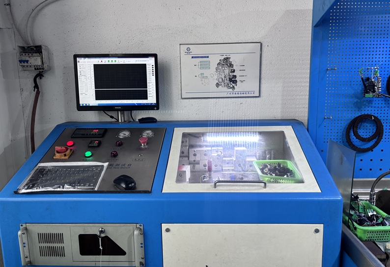
Most "tested" valve bodies are tested the same way: bolt it to a plate, spin the pump, watch a gauge move, box it. That catches a stuck spool and a dead solenoid. It does not catch the failure that actually happens on this platform — a bore that has worn oval and cross-leaks under load while still reading normal on a gauge at idle. This page is the procedure we run, in the order we run it, with the published acceptance numbers and the reject criteria attached to each step, so a workshop can either repeat it or audit a test sheet that arrives with a unit.
What this page gives you
- The published main line pressure values for the JF015E and the conditions they are only valid under.
- A tap map — which port reads which circuit, and which ports are not tapped at all.
- The solenoid resistance window at 20, 50 and 80 °C, and why a cold-only test passes failing coils.
- The vacuum step that separates a real remanufactured unit from a cleaned one.
- What a bench cannot prove, and what the installer still has to complete in the car.
01What a bench test can and cannot prove
The bench is a controlled hydraulic and electrical environment. It can set a known pump speed, a known fluid temperature and a known solenoid command, and it can measure the result without a vehicle, a transmission case or a driver in the loop. That is exactly why it is useful: it removes the variables that make an in-car diagnosis ambiguous.
What it cannot do is load the belt. A valve body on a bench has no cones to clamp and no torque to transmit, so it cannot prove that secondary pressure is sufficient to hold a belt at 150 Nm. It can only prove that the valve body delivers the pressure the specification asks for under the three classic conditions, and that nothing leaks down while it does.
| What you want to know | Bench can prove it | Needs the car |
|---|---|---|
| Solenoid coil integrity at operating temperature | Yes — heat-soak and re-measure | — |
| Regulator bore leakage past a worn spool | Yes — vacuum test per circuit | — |
| Main line pressure at idle and at stall | Yes, if the bench has a load absorber and a stall fixture | Can also be done in car at the pressure taps |
| Correct pressure at a commanded ratio under torque | No | Yes — live data, commanded versus actual ratio |
| Converter lock-up under load | No | Yes — steady-throttle lock-up and slip data |
| Cooler or cooler-circuit restriction | Partially — flow check only | Yes — temperature behaviour in service |
| Calibration load and post-install initialization | Load can be verified | Yes — the erase and load sequence runs in the car |
Read that table as a division of labour rather than a limitation. The bench exists to make sure the unit is not the problem before it ships; the car exists to make sure the installation and adaptation are right afterwards.
02The three pressure conditions and the published limits
JF015E main line pressure is checked in three states. The figures below are the ones published in the ATSG CVT 7 technical service information for the JF015E / RE0F11A / F1CJB, and they are measured at the secondary pulley pressure tap — which is not an arbitrary choice, because on this transmission the secondary pulley circuit is main line pressure. It feeds the primary pulley regulator valve, the solenoid regulator valve, the TCC regulator valve and the TCC control valve. One gauge on that circuit tells you about the health of the whole hydraulic supply.
| Condition | Main line pressure | In psi | What a reading outside the band suggests |
|---|---|---|---|
| P/N at idle | 5 bar | 72.5 psi | Low: regulator valve or bore wear, solenoid feed loss, pump wear. High: boost or regulator sticking |
| D/R at idle | 5–13 bar | 72.5–200 psi | Low: secondary circuit leakage under the load of an engaged range. High: regulator not trimming |
| D/R at stall | 41.8–46.8 bar | 607–680 psi | Low: the classic worn secondary pulley / pressure regulator bore signature. High: boost circuit fault |
Three notes that matter more than the numbers themselves. First, the D/R idle figure is a band, not a target — line pressure legitimately moves with ratio and load, so a unit reading 8 bar is not "wrong" because it is not 5. Second, the stall figure is the one that finds real wear: a unit can sit perfectly at 5 bar in P/N and still fall short at stall, because leakage past a spool scales with pressure. Third, the stall condition generates heat extremely fast on a CVT — hold it only as long as your test procedure allows, watch fluid temperature, and never repeat it back-to-back without letting the unit cool.
These values are only comparable at operating fluid temperature, with the correct NS-3 fluid at the correct level, and with a gauge of known accuracy. A cold unit, an over-filled unit or an uncalibrated gauge will produce numbers that look like a fault and are not. Record fluid temperature on the test sheet next to every pressure reading — a test sheet without it is a story, not data.
03Where the test points are, and what each one reads
The JF015E case gives you two tapped pulley pressure points and one high clutch pressure port, plus a set of untapped ports that require an adapter. Knowing which is which prevents the most common bench error: reading a circuit that is not the one you think you are reading.
| Test point | Circuit | Tapped from outside | What it is used for |
|---|---|---|---|
| Secondary pulley pressure tap | Secondary pulley / main line | Yes | The three acceptance readings above; the primary indicator of regulator and bore health |
| Primary pulley pressure tap | Primary pulley | Yes | Primary regulator response; comparison against secondary to see if the ratio control is being starved |
| High clutch pressure port | High clutch (auxiliary gearbox) | Yes | Confirms the auxiliary section is being fed and released correctly |
| TCC apply / release ports | Converter charge and lock-up | No — adapter required | Converter apply and release behaviour; usually tested indirectly through the TCC solenoid |
| Reverse clutch port | Reverse brake | No — adapter required | Reverse engagement pressure and release |
| Cooler in / out | Cooler circuit | No — line fittings | Flow and restriction check, not a pressure acceptance point |
There is also a partial drain plug on the case, which is useful for sampling fluid before the unit goes on the bench — sample first, because the fluid that comes out tells you whether the unit is worth testing at all.
04Electrical pass: five solenoids, two temperatures
The electrical pass is where a thin "tested" claim usually breaks down, because it is easy to do half of it. A coil measured at 20 °C can sit neatly in the middle of its window and still fail at 80 °C, which is the temperature it will actually live at. The published windows move with temperature by design — copper resistance rises as the coil heats — so the test is not "does it read 5.3 Ω", it is "does it read what it should at the temperature it is at".
| Solenoid | Type | 20 °C | 50 °C | 80 °C | Reject if |
|---|---|---|---|---|---|
| Line pressure A | Normally high | 5.3 Ω | 6.0 Ω | 6.7 Ω | Open, shorted, or drifting outside the window as it heats |
| Primary pressure B | Normally high | 5.3 Ω | 6.0 Ω | 6.7 Ω | Same, plus any coil that changes by more than the window across the heat soak |
| High clutch & reverse brake G | Normally high | 5.3 Ω | 6.0 Ω | 6.7 Ω | Same |
| Low brake F | Normally low | 5.3 Ω | 6.0 Ω | 6.7 Ω | Same |
| TCC | Normally low | 6.1 Ω | 6.9 Ω | 7.7 Ω | Same — note the TCC coil sits on a different window from the other four |
Each solenoid is internally grounded, so resistance is measured from the case connector terminal to the case, and from the internal harness terminal to the harness bracket when you are checking the harness instead of the coil. A reading that is correct at the case connector but wrong at the harness connector is a harness fault, not a solenoid fault — and it is worth the extra two minutes, because replacing a good solenoid does not fix a chafed wire.
Resistance is only half the electrical pass. The other half is actuation and sealing: command each solenoid and confirm it changes state audibly or by flow, then check it does not leak past when de-energised. A coil with perfect resistance and a stuck poppet passes every multimeter test and none of the ones that matter.
05Sensors: the two that decide whether the TCM trusts the unit
The valve body carries the fluid temperature sensor and the secondary pulley pressure sensor, and both feed the TCM directly. A drifting sensor does not produce a hydraulic symptom; it produces a control strategy that looks like a hydraulic symptom, which is worse, because it sends the next technician after the wrong part.
| Sensor | Condition | Expected value | What drift causes |
|---|---|---|---|
| CVT fluid temperature | 20 °C (68 °F) | 2.00 V or 6.5 kΩ | Fluid degradation logic and warm-up strategy shift; line pressure is scheduled from a temperature the TCM believes, not the one that is real |
| 50 °C (122 °F) | 1.50 V or 2.2 kΩ | ||
| 80 °C (176 °F) | 0.90 V or 0.87 kΩ | ||
| Secondary pulley pressure | Idle in neutral | 0.88–0.94 V (ATSG) | Closed-loop pressure control chases a false value; ratio and clamp complaints with no hydraulic cause |
On the pressure sensor we deliberately give a range and a condition rather than a single pass mark, because published figures differ by what they measure. The ATSG material gives 0.88–0.94 V at idle in neutral; an aftermarket rebuild guide gives 0.48–0.52 V for the zero position. Those are two different states — pressurised idle versus no applied pressure. The correct bench practice is to log the voltage at zero pressure and again at idle, check that both are inside their own reference, and check that the sensor moves smoothly between them. A sensor that reads plausibly at one point and flat-lines at the other is failing.
06The vacuum step that catches what a gauge cannot
Here is the part of the process that separates a reconditioned valve body from a cleaned one. A worn spool bore does not fail a pressure test at idle, because at idle the leakage is a small fraction of the volume being delivered. It fails a vacuum test, because vacuum asks the circuit to hold with nothing pushing back.
The method is simple and unforgiving. With the valve body clean and dry, apply vacuum to the test port for each regulator circuit — secondary pulley / pressure regulator, primary pulley regulator, solenoid regulator — and watch the gauge. A healthy bore and spool hold. A worn one bleeds down, sometimes slowly, sometimes in seconds. The published vacuum test guide for this unit specifies which port belongs to which circuit and the minimum each should hold; use those figures rather than a rule of thumb, because the circuits are not identical.
| Vacuum result | What it means | Action |
|---|---|---|
| Holds at or above the guide's minimum | Bore and spool are within tolerance | Pass — continue to flow and pressure |
| Bleeds down slowly but stays above half the minimum | Early wear; will leak under load and get worse | Ream and fit an oversized valve, or reject the core |
| Bleeds to zero quickly | Significant bore or spool wear, or a missing end plug | Reject unless the oversize range covers it |
| Will not pull vacuum at all | Passage blocked, plug missing, or the wrong port being tested | Re-check the port map before condemning the body |
This is also the step customers never see, which is precisely why it is worth asking about. "Fully tested" means nothing specific. "Vacuum-tested on the secondary, primary and solenoid regulator circuits, and reamed where it failed" means something you can hold a supplier to.
07The bench sequence, with reject criteria at every step
Order matters. Electrical before hydraulic, because a dead solenoid makes every pressure reading meaningless. Vacuum before flow, because a leaking bore makes a flow number look acceptable while hiding the leak. Pressure last, because it is the only test that requires the unit to be fully assembled and correctly calibrated.
| # | Step | What is measured | Reject criteria |
|---|---|---|---|
| 1 | Incoming inspection | Version, casting condition, cap type, contamination in the ports | Wrong family, cracked or heat-damaged casting, belt debris packed into a passage |
| 2 | Electrical, cold | Five solenoid resistances at 20 °C; sensor resistance | Any coil outside the 20 °C window; sensor open or shorted |
| 3 | Heat soak and electrical, hot | Same measurements at operating temperature | Any coil that moves outside its hot window; any intermittent open |
| 4 | Actuation and seal | Solenoid response to command; leakage when de-energised | No response, slow response, or leakage past a closed poppet |
| 5 | Bore vacuum | Each regulator circuit against the published minimum | Any circuit that will not hold; ream-and-oversize or reject |
| 6 | Valve freedom | Every spool stroked in its bore; springs checked | Stick-slip, scoring, spring out of free length or rate |
| 7 | Assembly and calibration | Gaskets, separator plate, end plugs, calibration load verified | Calibration will not load or does not match the version |
| 8 | Pressure at three conditions | P/N idle, D/R idle, D/R stall at the secondary tap | Outside 5 bar / 5–13 bar / 41.8–46.8 bar respectively |
| 9 | Leak-down and flow | Pressure decay across the test window; flow per circuit | Any decay trend, or flow below the circuit's reference |
Nine steps, and only one of them produces a number a customer would recognise. That is the nature of this work: the visible test is the least informative one.
08What still has to happen in the car
A bench-tested valve body is a proven component, not a proven repair. After installation the TCM has to be initialised, the calibration data loaded, the fluid degradation counter reset and the clutch points relearned. These are not optional courtesies; a unit installed without them will often drive badly enough that the customer concludes the part is faulty. We cover the exact sequence in the programming and relearn article, and the short version is: engine stopped, selector in R, accelerator depressed, sequence completed inside the scan tool's window, then a relearn drive cycle at operating temperature.
Three physical things also belong to the installation rather than the bench. The cooler circuit must be flushed, because a cooler full of debris from the failed unit will feed that debris straight into the new one. The pan magnets and filter must be renewed — reusing a loaded filter is a scheduled second failure. And the fluid must be NS-3, at the correct level, checked at 35–45 °C by the overflow method. NS-2 and generic ATF are not substitutes on this unit.
| In-car completion step | Why it decides the outcome |
|---|---|
| Cooler and cooler-line flush | Debris from the failed unit is the most common cause of a repeat failure within weeks |
| New pan filter and gasket, cleaned magnets | A loaded filter starves the pump and mimics a failing valve body |
| NS-3 fill and level check at 35–45 °C | Wrong fluid or wrong level changes every pressure the bench just validated |
| Calibration erase and load | The unit carries solenoid calibration data; the TCM has to be told about it |
| Clutch point relearn drive cycle | Without it the auxiliary gearbox engagements stay harsh and the customer blames the part |
| Post-repair code check and live data | Confirms commanded versus actual ratio and that no pending code returns |
09How to read a test sheet that arrives with a unit
If a supplier sends test data, the sheet is worth more than the warranty card — but only if it contains enough to be falsifiable. Nine fields separate a real record from a decorative one.
| Field | Why it matters |
|---|---|
| Unit identification and version | Ties the data to the casting you received, not to a generic model |
| Fluid temperature at test | Pressure and resistance are both temperature-dependent; without it the numbers cannot be judged |
| Five solenoid resistances, cold and hot | Proves the hot test was actually done |
| Sensor voltages at zero and at idle | Proves the sensors were checked in two states |
| Vacuum result per regulator circuit | The single strongest indicator that bores were assessed, not just cleaned |
| Line pressure at idle P/N, idle D/R, stall D/R | Shows the three-condition test rather than a single idle reading |
| Leak-down over a stated interval | Distinguishes a unit that holds from a unit that merely starts high |
| Parts replaced, by name | Separates a rebuild from a reseal |
| Technician and date | Makes the record accountable |
A sheet missing the fluid temperature and the vacuum results is a checklist, not a test record. That is not a reason to reject a unit on its own — plenty of good rebuilders keep records internally and do not ship them — but it is a fair question to ask before the second order.
10Fluid and assembly figures used around the bench
These are the numbers that get used every time a JF015E valve body comes off and goes back on. They are listed here because they are frequently repeated wrongly, and because a bench result is meaningless if the unit is filled with the wrong fluid or assembled to the wrong figure.
| Item | Figure | Note |
|---|---|---|
| Fluid specification | Nissan NS-3 only | NS-2 and generic ATF are not substitutes; using them is a documented cause of damage |
| Total fluid capacity | 6.9 L (7 1/4 US qt) | Total fill, not a drain-and-refill quantity |
| Level check temperature | 35–45 °C | Overflow method, engine running, selector cycled through the range |
| Overflow tube | 3.5 Nm | Small fastener, easy to overtighten |
| Drain plug | 34.3 Nm | With a new gasket, at the end of the operation |
| Valve body retaining bolts | 7.5 Nm per published aftermarket install guidance (or torque-to-angle 40°) | Your model year's service data governs; the point is that these are low-torque fasteners, not "tight" |
| Bolts not to be removed | The 4-marked bolts | Only the 11 bolts marked 7 come out to release the assembly; the 4-marked bolts hold the body itself together |
That last row has saved more valve bodies than any torque figure on this page. Removing the 4-marked bolts separates the body's own sections, spills the spools onto the bench in an order nobody recorded, and turns a testable unit into a puzzle.
Main line pressure values for P/N idle, D/R idle and D/R stall, the solenoid resistance windows at 20 °C, 50 °C and 80 °C, the fluid temperature sensor values, the secondary pulley pressure sensor reference, the total fluid capacity of 6.9 L, the 35–45 °C level-check window, the 3.5 Nm overflow tube and 34.3 Nm drain plug figures, the pressure tap locations and the 11-bolt / 4-bolt valve body removal note all come from the ATSG CVT 7 JF015E / RE0F11A / F1CJB technical service information (2015). Circuit relationships and the vacuum test method follow Sonnax technical material for this unit, including the published secondary pulley / pressure regulator and primary pulley regulator oversize valve kits and the vacuum test guide referenced against them. The 7.5 Nm valve body fastener figure and the 40-degree torque-to-angle alternative come from published aftermarket installation guidance and are labelled as such; the factory service data for the specific model year governs. Where published sources give different sensor references for different conditions, both are shown rather than reconciled.
11Sources and frequently asked questions
What is the correct line pressure for a JF015E?
At the secondary pulley pressure tap, which is main line pressure on this unit: 5 bar (72.5 psi) at idle in P/N, 5–13 bar (72.5–200 psi) at idle in D/R, and 41.8–46.8 bar (607–680 psi) at stall in D/R. The D/R idle figure is a legitimate band, not a single target, because line pressure varies with ratio and load. All three are only comparable at operating fluid temperature with NS-3 at the correct level and a gauge of known accuracy.
Why test solenoids at two temperatures?
Because copper resistance rises with temperature and the specification is written that way: 5.3 Ω at 20 °C, 6.0 Ω at 50 °C and 6.7 Ω at 80 °C for the four pressure and shift solenoids, 6.1 / 6.9 / 7.7 Ω for the TCC solenoid. A coil can sit perfectly in its cold window and fail when hot, which is the state it spends its life in. A cold-only test is half a test.
What does a vacuum test prove that a pressure test does not?
It proves the bore and spool can hold. Under pressure, a worn bore leaks a small percentage of the delivered volume and the gauge still reads normally, especially at idle. Under vacuum there is nothing pushing back, so any leakage is visible immediately. This is the check that distinguishes a valve body whose bores were assessed from one that was cleaned and painted.
Can a bench test prove the valve body will fix the car?
No. It proves the unit delivers specified pressure at idle and at stall, that the solenoids work hot and cold, that the sensors read plausibly and that the bores hold. It cannot load the belt, so it cannot prove clamp force under torque, and it cannot prove converter lock-up under load. Those are confirmed in the car with live data after the initialization and relearn.
Do I have to remove the 4-marked bolts to take the valve body off?
No — and you should not. The assembly is released by the 11 bolts marked 7. The 4-marked bolts hold the valve body's own sections together; removing them separates the body and frees the spools in an order that is hard to reconstruct. If a unit arrives with those bolts disturbed, treat it as a core that has been opened, not as a tested assembly.
What fluid goes back in, and how much?
Nissan NS-3 only. Total capacity is 6.9 L (7 1/4 US quarts); the level is set by the overflow method with the fluid at 35–45 °C, engine running, selector cycled through the range. The overflow tube is tightened to 3.5 Nm and the drain plug to 34.3 Nm with a new gasket. NS-2 and generic ATF are not substitutes on this transmission.
How long should a stall test be held?
Only as long as your test procedure allows, with fluid temperature watched throughout. A CVT generates heat very quickly at stall because the belt is clamped and slipping against a stationary output, and the fluid has nowhere to carry that heat fast enough. Back-to-back stall tests on the same unit are how a good valve body gets cooked on a bench.
Can you send the bench data with a JF015E valve body?
Yes. Ask for it when you order and we will include the record for your unit: version identification, fluid temperature at test, five solenoid resistances cold and hot, sensor voltages, vacuum results per regulator circuit, and line pressure at idle P/N, idle D/R and stall D/R. Minimum order is one piece, all units are tested on a computerised bench before dispatch, and the written warranty runs 12 months.